The functions currently available have their standard meanings. (See Standard Keyword Top Level Menu Options)
Generic keyword editing is also available.
Nodes ("grid points") form the vertices of elements and wide range of other structural purposes: they are the "glue" that holds a finite element model together. Within an LS-Dyna analysis virtually all mass is lumped at nodes, providing a simple mass vector that doesn't require matrix inversion: the basis of the "explicit" solution method.
Special rules apply to the eligibility of nodes for screen-picking: they do not have to be drawn explicitly to be pickable: see the "Rules for screen-picking nodes" below.
The following special operations may also be performed on nodes.
| Replace | Allows you to replace node A with node B |
| Drag | Allows nodes to be dragged, morphing the model, using a range of geometrical and topological rules. |
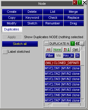
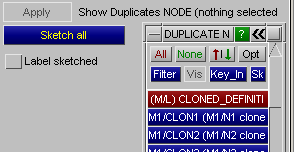
| Duplicates | When nodes have been multiply defined in different include files PRIMER merges them together using the same coincidence rules as LS-DYNA, creating "clone" definitions so that they are remembered. This option allows you to sketch and label these duplicated nodes. |
|
The nodes menu
allows the creating,
modification etc. of nodes in a keyword deck.
The functions currently available have their standard meanings. (See Standard Keyword Top Level Menu Options)
Generic keyword editing is also available. |
|
CREATE Making new node(s)There are eight possible ways of creating nodes. These are selected by right clciking below . The following options are available |
|
The default node label used is the highest node label in the model + 1.
Picking a node from the screen will set the X, Y and Z fields for the node you are creating to be the coordinates of the picked node. Alternatively you can just type in a new value for the X, Y or Z coordinate in the boxes.The default coordinates used are (0.0, 0.0, 0.0).
The node label can be changed by typing in a new value or using the popup. If needed translational and rotational restraints can be applied by typing the value into the TC and RC fields or by using the popups.
Instead of creating a single node, you can create any number of nodes in a line between 2 existing nodes.
Initially the two end nodes are undefined so will be shown as <none> on a red background. Picking a node from the screen will update one of the two end nodes. The one which will be updated is shown in yellow instead of white, so in the figure to the right, Node 1 will be updated if a node is picked. Once this is picked then node 2 will be highlighted and can be picked from the screen. The two nodes can alternately be picked from the screen in this way.
Any number of nodes can be created between the 2 end nodes. Either use the popup or type in a number to select how many to create. In this figure 4 nodes will be created.Alternatively you can type in a node number or use the popups to create, select, sketch etc a node.
Once both end nodes have been defined the button will become active and can be used to create the nodes. The display will then refresh for you to create another line of nodes. Once you have finished will close the window.
Creating a surface of nodes works in an identical way to creating a line of nodes except that 4 nodes need to be defined (one at each corner) and the number of nodes to create can be varied in both directions.
In this figure node 1 is the node currently highlighted for picking, and 4 nodes will be created in one direction, 5 in the other.
The nodes do not need to be on a plane. If the nodes are not then the nodes will be generated on a curved surface between the 4 nodes.
Creating a node at the centre of a circle works in an identical way to creating a line of nodes except that 3 nodes need to be defined.
In this figure node 1 is the node currently highlighted for picking. The 3 nodes define a circle, and the node created will be at the centre of that circle.
This method of creating a node only requires the user to select one node. This node must be on the free edge of a hole. PRIMER will determine the centre of the hole and create the node there when clicking on .
This method of creating a node requires the user to screen pick one geometry point. An 'auto-create' option is also available that obviates the need for clicking on .
Instead of creating nodes by picking one geometry point at a time, users may select multiple geometry points from a menu or off the screen. New nodes are then created at the location defined by all these geometry points. As in the case of the single geometry point method, an 'auto-create' option is available that obviates the need for clicking on .
Multiple geometry curves may be selected. PRIMER will then create the desired number of nodes spaced equidistantly along each of these geometry curves.
| DISMISS | Aborts the current definition and returns to the main nodes menu. |
| RESET_ALL | Resets all attributes to <null> for this definition: all data entered will be lost, and the panel will return to its initial default state. |
| COPY_EXISTING | Copies the attributes of an existing node definition (in the current model). This may then be modified as required. |
| SKETCH | Sketches the current definition on top of the current image. |
| LIST_XREFS | Lists everything that references the current node definition. |
| CHECK_DEFN | Performs a check of the current definition, listing any errors. |
| CREATE_NODE | Saving the node definition. Once you have entered the node information the button will save this definition. The definition will be checked and any errors listed, an then it will saved permanently in this model. Until you press this the definition remains volatile, and will be lost if you exit this panel in any other way. Once the node(s) has been defined the panel will refresh with the default values to speed up node creation. |
You can any number of nodes, in multiple models.
When is pressed you are asked to confirm what is to be copied, and then the operation is carried out.
For each model the <n> extra nodes chosen in that model are copied using labels <previous highest + 1> to <previous highest +n>, there is currently no control available over the new labels assigned.
This functions in exactly the same way as CREATE , using the same panels as in the figures above. The only difference is that the initial state of the panels is already set with the attributes of the node to be modified. In the modify mode the options to create nodes along a line or surface are not available. Only a single node can be modified.
If you want to change values on multiple nodes then you should use the option instead
The operation works exactly the same way as above, except that the chosen nodes are deleted.
Note also that the standard deletion rules described in DELETE UNWANTED still apply: nodes will only be deleted if nothing else (which is to remain) depends on them.
starts the generic keyword editor which allows creation, deleting and modification of multiple nodes. This is useful for modifying multiple nodes in a single operation.
allows the user to select and sketch individual nodes on the current graphics image. Nodes are drawn with a star symbol.
Runs the standard checking function on the selected nodes. Each node will be listed either as "OK", or a summary of the errors encountered will be printed. (This is the same as the command during node editing.)
Writes a summary list of the selected nodes to the screen. This is just the total number of selected nodes in each model.
Raises the standard renumbering panel for nodes in the chosen model, allowing you to renumber some or all of them.
allows you to merge coincident nodes (or nodes within a specific tolerance) together. For more information see the MERGE NODES option in the REMOVE window.
works in an identical way to MERGE but only allows you to replace a single node with another node.
|
'quick picking' is enabled in the replace node panel so you can just
click on the screen to select the 2 nodes. The node which you are currently
picking is shown by the colours being inverted (i.e. in the figure on
the right, node A is currently being picked).
Alternatively you can type in the node numbers or use the popup to select the nodes If is selected then the node will be replaced as soon as both nodes are given. Alternatively press to replace the node. |
|
| By default the label of the second node you pick (B) will be kept. You can change this by using the popup. You can choose to keep either label or the highest or lowest label. |
|
| By default the node will be replaced at the location of the second node you pick (B). This can be changed by using the popup. You can force the node location to be at the position of either node A or B, the average position, or the position of the node with the lowest or highest label. |
|
returns the user to the main PRIMER window
permits users to drag nodes based on certain constraints. The impact of such an operation on element quality can be viewed using the button. Various individual quality metrics, as well as overall quality imperfection can be viewed using the button.
|
Four methods are currently available for node dragging:
|
|
|
The button will instruct PRIMER to automatically reposition nodes for improved quality. Two optimisation modes are available - single and multi node. The latter permits selection of one or more elements. PRIMER will then reposition attached nodes so that overall quality of the selected elements is improved. Nodes that lie on a free edge or feature line can be restrained using an appropriate option. Movement of nodes that also lie on unselected elements can also be restricted using an option.
|
|
DUPLICATESSketching and labelling duplicate coincident nodes, sometimes used to "stitch" models together. Coincidence rulesLS-DYNA has special rules to handle the case that node label N is defined more than once in different include files. It merges multiple definitions of node N into a single definition so long as:
The test for "coincidence" of two definitions NA and NB with the same label is as follows:
xdist1 = max(1.0e-16, vector distance of node from
origin)
xdist2 / xdist1 < 1.0e-8 In addition if a *NODE_MERGE_TOLERANCE card has been defined then the distance xdist2 must be greater than this tolerance value for the nodes to be considered "not coincident". PRIMER uses the same rules as LS-DYNA. |
|
|
How coincident nodes are handled inside PRIMERPRIMER has the problem that nodes must be merged if coincident, but also that the duplicate definitions must be "remembered" so that they are written out again in the correct include files. It handles this by creating "clone" definitions of each node such that:
Coincident nodes are normally merged silently during keyword input, but it is possible to list nodes merged during this process by using the "Save keyin log to file" option. |
|
Visualising duplicate nodesSince duplicate nodes are actually just references to the true node definition they do not appear as separate entities on plots, nor will you see them in menus that list nodes. However they can be sketched and labelled using this option. Either to show all of them, or select the subset of nodes to be seen from the menu of cloned nodes and to draw them. By default only node symbols are shown, but will also turn on labels, which shows both node label and also the include file in which it resides. |
|
Node visibility and labelling is controlled from the ity Viewing menu.
However its treatment is different to that applied to all other item types.
| ALL_NODES | Draws all nodes, regardless of attachment |
| ATTACHED | Draws only nodes attached to items currently visible on the screen |
| UNATTACHED | Draws nodes that are not attached to any item. |
Labelling of nodes is handled in much the same as their drawing.
Nodes do not have to be drawn explicitly in order to be labelled: for example selecting labels will display the node labels on visible elements etc.
Dynamic labelling and details of nodes |
|||||
|
As with elements, nodes have a special "pick to label and display details box" that is invoked by clicking on one of the
or from Quick Pick. You can control how nodes are labelled and drawn using: Label with...
Draw with...
|
||||
Nodes are treated in a non-standard way for screen-picking purposes. A node is pickable if:
The second condition may be thought of as " ATTACHED ", without actually having to draw the nodes.
The reason for this anomaly is that it is extremely useful to be able to screen-pick nodes, but very annoying if they have to be drawn to make this possible: node symbols tend to obscure other useful information, and also slow down graphics.